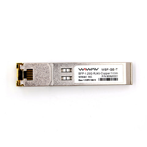
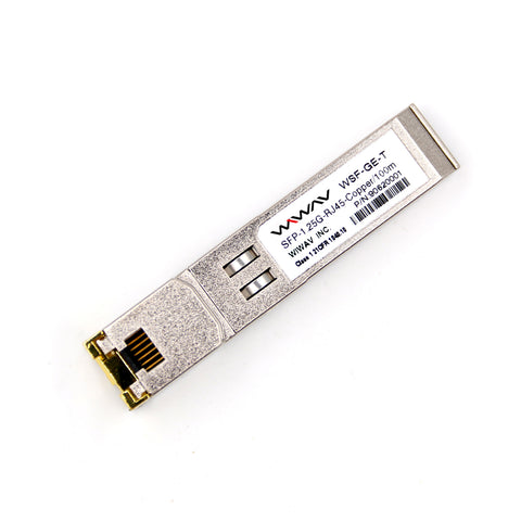
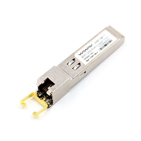
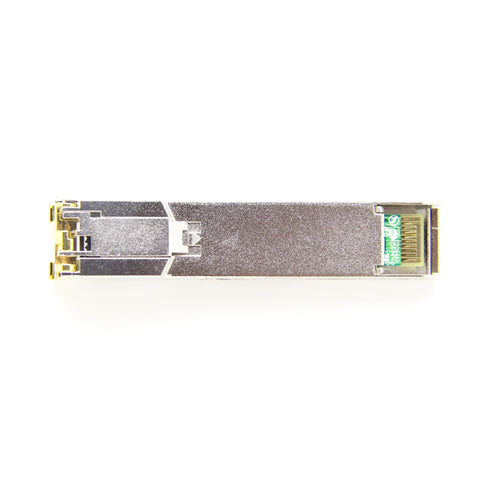
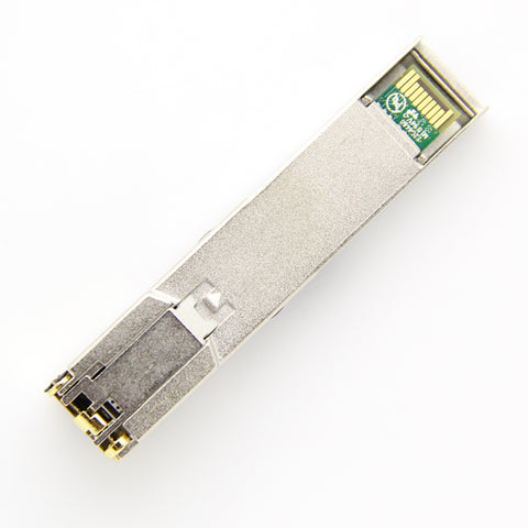
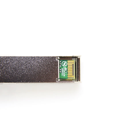
WSF-GE-T 1000BASE-T Copper SFP Transceiver
$69.98
$99.98
Pickup currently unavailable
Product Features
- Up to 1.25 Gb/s bi-directional data links
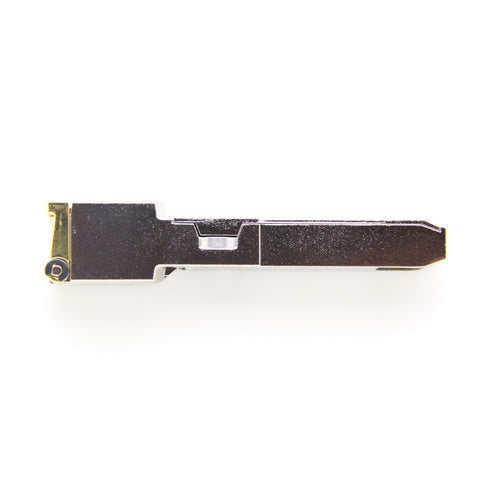
- Hot-pluggable SFP footprint
- Low power dissipation (1.05 W typical)
- Compact RJ-45 connector assembly
- Fully metal enclosure for lower EMI
- RoHS compliant and lead-free
- Single +3.3 V power supply
- 1.25 Gigabit Ethernet over Cat 5 cable
- Case operating temperature:
- Commercial: 0 °C to +70 °C
- Extended: −10 °C to +80 °C
- Industrial: −40 °C to +85 °C
Product Description
WIWAV’s WSF-GE-T 1000BASE-T Copper Small Form Pluggable (SFP) transceivers are based on the SFP Multi Source Agreement (MSA).
They are compatible with the Gigabit Ethernet and 1000BASE-T standards as specified in IEEE Std 802.3. The 1000BASE-T physical layer IC (PHY) can be accessed via I2C, allowing access to all PHY settings and features.
The WSF-GE-T uses the RX_LOS pin for link indication, and 1000BASE-X auto-negotiation should be disabled on the host system.
SFP to Host Connector Pin Out

| Pin | Name/Description | Note |
|---|---|---|
| 1 | VEET — Transmitter Ground (Common with Receiver Ground) | 1 |
| 2 | TFAULT — Transmitter Fault. Not supported. | |
| 3 | TDIS — Transmitter Disable. Not supported. | |
| 4 | MOD_DEF(2) — Module Definition 2. Data line for Serial ID. | |
| 5 | MOD_DEF(1) — Module Definition 1. Clock line for Serial ID. | |
| 6 | MOD_DEF(0) — Module Definition 0. Grounded within the module. | |
| 7 | Rate Select — No connection required | |
| 8 | LOS — Loss of Signal indication. Logic 0 indicates normal operation. | 2 |
| 9 | VEER — Receiver Ground (Common with Transmitter Ground) | 1 |
| 10 | VEER — Receiver Ground (Common with Transmitter Ground) | 1 |
| 11 | VEER — Receiver Ground (Common with Transmitter Ground) | 1 |
| 12 | RD− — Receiver Inverted DATA out. AC Coupled | |
| 13 | RD+ — Receiver Non-inverted DATA out. AC Coupled | |
| 14 | VEER — Receiver Ground (Common with Transmitter Ground) | 1 |
| 15 | VCCR — Receiver Power Supply | |
| 16 | VCCT — Transmitter Power Supply | |
| 17 | VEET — Transmitter Ground (Common with Receiver Ground) | 1 |
| 18 | TD+ — Transmitter Non-Inverted DATA in. AC Coupled | |
| 19 | TD− — Transmitter Inverted DATA in. AC Coupled | |
| 20 | VEET — Transmitter Ground (Common with Receiver Ground) | 1 |
Notes:
1) Circuit ground is connected to chassis ground.
2) Should be pulled up with 4.7k - 10k Ohms on host board to a voltage between 2.0 V and 3.6 V. MOD_DEF(0) pulls line low to indicate module is plugged in.
3) LVTTL compatible with a maximum voltage of 2.5 V.
+3.3 V Electrical Power Interface
| Parameter | Symbol | Min | Typ | Max | Unit | Note |
|---|---|---|---|---|---|---|
| Supply Current | Is | 320 | 375 | mA | 1.2 W max power over full range of voltage and temperature | |
| Input Voltage | Vcc | 3.13 | 3.3 | 3.47 | V | Referenced to GND |
| Maximum Voltage | Vmax | 4 | V | |||
| Surge Current | Isurge | 30 | mA | Hot plug above steady-state current |
Caution: Power consumption and surge current are higher than the specified values in the SFP MSA
Low-Speed Signals
| Parameter | Symbol | Min | Max | Unit | Note |
|---|---|---|---|---|---|
| SFP Output LOW | VOL | 0 | 0.5 | V | 4.7k to 10k pull-up to host_Vcc, measured at host side of connector |
| SFP Output HIGH | VOH | host_Vcc−0.5 | host_Vcc+0.3 | V | 4.7k to 10k pull-up to host_Vcc, measured at host side of connector |
| SFP Input LOW | VIL | 0 | 0.8 | V | 4.7k to 10k pull-up to Vcc, measured at SFP side of connector |
| SFP Input HIGH | VIH | 2 | Vcc+0.3 | V | 4.7k to 10k pull-up to Vcc, measured at SFP side of connector |
High-Speed Electrical Interface
Transmission Line — SFP
| Parameter | Symbol | Min | Typ | Max | Unit | Note |
|---|---|---|---|---|---|---|
| Line Frequency | fL | 125 | MHz | 5-level encoding, per IEEE 802.3 | ||
| Tx Output Impedance | Zout,TX | 100 | Ohm | Differential, 1 MHz to 125 MHz | ||
| Rx Input Impedance | Zin,RX | 100 | Ohm | Differential, 1 MHz to 125 MHz |
Host — SFP
| Parameter | Symbol | Min | Typ | Max | Unit | Note |
|---|---|---|---|---|---|---|
| Single-ended data input swing | Vinsing | 250 | 1200 | mV | Single-ended | |
| Single-ended data output swing | Voutsing | 350 | 800 | mV | Single-ended | |
| Rise/Fall Time (20–80%) | Tr, Tf | 175 | psec | 20%-80% | ||
| Tx Input Impedance | Zin | 50 | Ohm | Single-ended | ||
| Rx Output Impedance | Zout | 50 | Ohm | Single-ended |
General Specifications
| Parameter | Symbol | Min | Typ | Max | Unit | Note |
|---|---|---|---|---|---|---|
| Data Rate | BR | 10 | 1000 | Mb/s | IEEE 802.3 compatible. See Notes 2–4 below | |
| Cable Length | L | 100 | m | Category 5 UTP. BER |
Notes:
1. Clock tolerance is +/- 50 ppm
2. By default, the WSF-GE-T is a full duplex device in preferred master mode
3. Automatic crossover detection is enabled. External crossover cable is not required
4. WSF-GE-T does not support SGMII .With a SERDES the module will operate at 1000BASE-T only
1. Clock tolerance is +/- 50 ppm
2. By default, the WSF-GE-T is a full duplex device in preferred master mode
3. Automatic crossover detection is enabled. External crossover cable is not required
4. WSF-GE-T does not support SGMII .With a SERDES the module will operate at 1000BASE-T only
Environmental Specifications
| Parameter | Symbol | Min | Typ | Max | Unit | Note |
|---|---|---|---|---|---|---|
| Case Operating Temperature | Tcase | 0 | 70 | °C | WSF-GE-T | |
| Case Operating Temperature | Tcase | −10 | 80 | °C | WSF-GE-TE | |
| Case Operating Temperature | Tcase | −40 | 85 | °C | WSF-T-N | |
| Storage Temperature | Tsto | −40 | 85 | °C | Ambient temperature |
Serial Communication Protocol
WSF-GE-T supports the 2-wire serial communication protocol outlined in the SFP MSA. It uses an Atmel AT24C02B 256-byte EEPROM with an address of A0h.
Serial Bus Timing Requirements
| Parameter | Symbol | Min | Max | Unit | Note |
|---|---|---|---|---|---|
| I2C Clock Rate | 0 | 100,000 | Hz |
Mechanical Specifications (Unit: mm)
